If you don't think it'll work let me know what I missed.


lonewolf wrote:Assuming that the upper pup is the neck and the pins on the switch go 1,3,5,COM from top to bottom. In schematic jargon these labels are known as reference designations and pin outs.
Your neck pickup will only have coil split in position 2.
The .001uF capacitor will only have an effect as you turn your volume down.
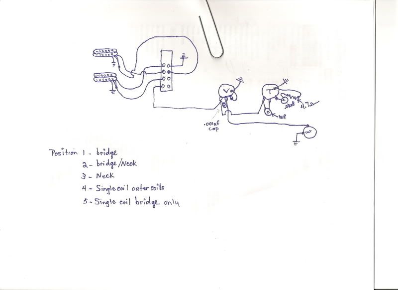
1.Bridge humbuckermetalchurch wrote:Generally your positions @ your switch work their way from back to front like this:
1. Bridge
2. Bridge (split to single coil)
3. Bridge + Neck
4. Single coil (outer coils)
5. Neck
I'm alittle confused about a few things though.
The Bridge + Neck, is that Full Humbuckers?
The Single Coil (outer coils) are the bridge + neck split into single coils right?
The hum cancelling effect will be lessened by the difference between the 2 pickup's output levels. If the neck pickup has about half the output of the bridge (when no string signal is present), it will only cancel about half of the noise signal. This will be roughly proportional to the DC resistance values.tonefight wrote: I think I drew my switch backwards but if I get one in my hands I'll get it right. Position 5 will pretty much be worthless but position 4 is what I was after. Position 4 should give me humcamcelling single coils in parallel.